Serial data communication -
glossary, terms and definitions
In this article, you may find an overview of the terms refering to the serial data communication. If you cannot find the answer here, please feel free to contact our technical support.
Serial data communication standards
Although the following standards have been renamed several times (by EIA, TIA), they are well-known under the original designation "RS" (recommended system).
RS-232
The RS-232 interface is intended for the data transmission over distances to tens of meters and baud rates up to tens of kBd. A single-ended signaling with common GND is used for the transmission. The operating voltage levels are 3÷15V for L state and -3÷15V for H state. Two basic signals TXD and RXD are used for the data transmission, the other signals can be used for the transmission control - request to send (RTS), clear to send (CTS), data terminal ready (DTR), and data set ready (DSR).
Since transmit data and receive data are separate circuits, the interface can operate in a full-duplex manner, supporting concurrent data flow in both directions.
RS-485
The RS-485 interface is intended for the data transmission among several units in a network topology. However, it can be used for the point-to-point connections as well. In contrast to RS-232, the signalling at RS-485 is realised by a differential line. The two signals are labelled as TXD/RXD+ (sometimes B or non-inverting) and TXD/RXD- (sometimes A or inverting).
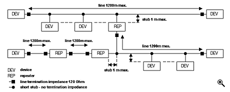
The RS-485 interface is intended for the data transmission up to 1200m; over less distances it supports the baud rates up to 10MBd. There can be connected up to 32 devices to one segment.
Considering the estimated costs when designing the communication line, the RS-485 interface is much less expensive, as it uses one twisted pair with cable impedance of 120 ohms. When realising line over short distances (several metres), a non-shielded cable can be used.
Note: Especially when using RS-485 isolated interfaces, it is strongly recommended to connect the GND terminals at both sides of the communication interface, e.g. through the cable shielding (see picture). Connecting the GND is strictly required by many standards (e.g. Profibus).
Since the RS-485 two-wire connection only allows half-duplex communication, all devices must be equipped with bidirectional drivers, and the device must generate an auxiliary signal for control of direction. From a software point of view, the device must have implemented a communication protocol that provides bus access to the line in time multiplex ("master-slave" mode with one busmaster, or "multimaster" mode with floating busmaster).
RS-485 impedance termination
To prevent undesirable signal reflections, the termination impedances are used. Typical termination impedances value for RS-485 is 120 ohms (corresponds the cable impedance). If the connection is realised on short distance (up to tens of metres), the termination impedance is not necessary.
All TEDIA communication cards and some selected converters provide the termination impedances as a standard feature. The impedances are always accessible through the connector pins or terminals.
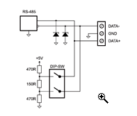
To ensure the correct signals voltage on the line when all drivers are in the receiving state (none of them are transmitting data), it is suitable to use the active terminating impedance (see figure below).
Note: All TEDIA communication cards and converters are equipped with active termination impedances.
RS-422
The RS-422 interface is half-way between RS-232 and RS-485 by its philosophy. Usually two sets of twisted pair (with same characteristics as at RS-485). The signals are labelled as TXD+ (B), TXD- (A), RXD+ (B) a RXD- (A). In the event of point-to-point topology, the RS-422 is full-duplex (just like RS-232) and the drivers don't need to be controlled. The controllers, baud rates and communication distances are identical to RS-485. There can be up to 10 receivers connected to one transmitter.
Some converters allow to transmit data using 4 sets of twisted pair. The two extra sets are usually used for transmitting the RTS and CTS signals.
As at RS-485, it is necessary to use the termination impedances at long distances. When using RS-422 at standard mode, the impedances at the transceiver side are not necessary (see picture). In the multimaster mode, the usage of the termination impedance is identical ti RS-485.
Note: There is the same recommendation for connecting the GND signals as at RS-485.
Safety guidelines for preventing overvoltage damage
The main reason of the transient overvoltage (sometimes shortened to transient) are atmospheric discharges. The transient overvoltage sources may rise from power and data communication lines. E.g. switching in power supply low voltage networks may result into transient overvoltage.
This transient may enter the device by by galvanic, inductive or capacitive coupling. To prevent the devices against transient overvoltage, it is necessary to obey several rules. The basic source for considering the risk of damage from atmospheric discharges is a set of standards EN 62305-1 to EN 62305-4 (Protection against lightning).
The three-level protection should be considered when realizing projects. Level 1 is usually consisted of lightning rods of buildings, an its use necessary when communicating over long distances outside buildings. Suitable product can be selected for instance in the DEHN + SÍHNE product line.
Level 2 is the protection located near to the protected area, e.g. at the input of the switchgear room). From the TEDIA product line it is recommended to use the combined protection based on surge arresters and TVS diodes - the module MU-3485.
Level 3 protection consists of fast TVS diodes located inside the protected room/device. This type of protection provide all TEDIA products featuring the RS-485 or RS-422 interface.
Also please realize that the isolation of the line interface circuits cannot be considered as the overvoltage protection. The optical isolation just suppress the occurrence of ground loops. In the event of inducting the overvoltage it cannot prevent the damage of the line interface circuits, but it successfully helps to prevent damages of the circuits located behind this isolation barrier.
Selected terms
Converter
Converters are devices intended for converting one communication line standard into another. They usually provide mutual isolation of the communication interfaces and at least one interface is isolated from the supply power source. The communication interfaces may equipped with additional overvoltage protection.
All TEDIA converters are always isolated, the industrial types provide the tri-state isolation (both interfaces are isolated from each other and both are isolated from the supply power source).
Repeater
The repeaters are in fact converters providing tho interfaces of the same standard. They are intended especially for isolating the selected network segments, for extending the transfer distance and in the event of RS-485 also for extending the number of connected devices.
All TEDIA repeaters provide the tri-state isolation (both interfaces are isolated from each other and both are isolated from the supply power source).
Surge Arrester
Surge arrester is a very effective protection suitable for realizing level 2 overvoltage protection. Due to tens (or hundreds) volts of the operating voltage, they cannot be used as the only line overvoltage protection. However, they cut down the inductive voltage to the level, that can by handled by other protection - TVS diodes.
The next usage of the surge arresters is the protection of the isolation barrier against overvoltage inducted to the line. The surge arrester does not protect the interface signals, but it is connected between signal GND (or shielding of the cable) and the ground. At TEDIA isolated communication cards, the surge arrester is connected between the cable shielding and the PC housing (ESD-X2 or ESD-X4 extension).
Transient Voltage Suppression diode (TVS) diode
The function principles are similar to Zener diode, but TVS diode is intended especially for the overvoltage peaks.
Although this type of protection enhances the immunity against overvoltage damage caused by inductive coupling into the line, it cannot be generally considered as the only sufficient protection.
For instance, it can be used as the only protection at the applications within one building in common environment. If the line is realised outside the building, or the signal wires are located in the area with strong electromagnetic interference, it is necessary to use also the other levels of protection (surge arrester modules, complex overvoltage protection of the communication lines, etc.).
Note: All TEDIA communication cards, repeaters and converters with the RS-422/485 interface provide the TVS diode overvoltage protection by default.
Optical isolation
Optical isolation is realised by optocouplers (sometimes as opto-isolator or photocoupler).
The main reason of using the optical isolation for communication lines is preventing the occurrence of ground loops (and therefore the occurrence of circulating currents).
The optical isolation of the line transceiver does not ensure any resistance against induced overvoltage to the line interface circuits. However, it notably prevents any damage to the circuits behind this isolation barrier.
The surge arresters can be used for protecting the isolation barrier circuits against induced overvoltage.


